RF Products’ 3-Point Product Program
At RF Products, we are ready to support your project at the level that makes the most sense for your project. We can provide the stand-alone tunable filters and multicouplers that you need. Or we can provide the complete M3B RFD with RFD RCU Digital Dashboard (R2D2™), including antenna model and location selections, and complete radio system performance analyses.
VHF/UHF TUNABLE FILTERS & MULTICOUPLERS
- Available as stand-alone products or as part of an M3B RFD.
- Tunable filters from 30 MHz to 2 GHz.
- Always-continued support of all legacy products.
- DMS is never an issue at RF PRODUCTS.
- All products Mil-Qualified for sea, air and/or land use.
- In-house design & vertically integrated manufacturing facilitates easy modifications of existing designs to meet your specific needs.
MULTI-MODE, MULTI-BAND, RF DISTRIBUTION SYSTEM (M3B RFD), with RCU & R2D2TM
- Holistic solution especially for Multi-Mode, Multi-Band (M3B) radios.
- Includes all hardware required between radios and antennas. (Excluding external cables and connectors.)
- With R2D2, Operators have a fast, easy way to reconfigure all mission comms without concerns for RF path selections or frequency conflicts.
- We test entire M3B RFD and RCU with radios and customer’s main comms control to confirm interfaces and waveforms compliance.
COMPLETE RADIO/M3B FRD/ANTENNA SYSTEMS DESIGN AND ANALYSES
- We can provide complete radio-M3B RFD – antenna design, and then work with you to refine it to maximize mission capability.
- We work with you on the RF analysis so that you “own it”.
- Our per-path analysis enables fast, easy corrections to the overall analysis if the M3B RFD design is changed, or if the first-pass analysis identifies shortfalls.
- We reduce your cost, risk and time to get to the facts related to:
- Cosite interference
- LOS Link Range
- SATCOM Link Margin
- Adjacent Channel Separation
1. TUNABLE FILTERS AND MULTICOUPLERS
Three families of filters and multicouplers in bands from 30 MHz up through L-Band. VCT and CCT Series are manual-controlled, or remotely-controlled-motor-tuned, passive resonant cavities. FLX Series are remotely controlled electronically tuned passive resonant cavities for use when fast tuning is required.
Variable Capacitor Tuned Series
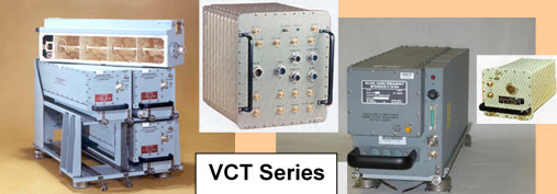
- (Air) Variable Capacitor Tuned filters (VCT). Typically 4 poles. RF PRODUCTS’ site has been in air variable capacitor design and production since 1921!
- A more compact package than CCT Series: more suitable for aircraft and platforms with limited rack space.
- Typical 5 second tune time
- Typical 2 dB insertion loss, depending on selectivity tradeoffs for narrow or wide passbands.
- Various filter cavity sizes available for range of tradeoffs on size/weight versus selectivity, power handling and insertion loss.
- Filter used in transmit and/or receive.
- High transmit power handling.
- Available in bands from 30 MHz to 512 MHz
- Available as single filters through 5-port multicouplers.
- Versions Mil-Qualified for sea, air, and land use.
- For use as stand-alone products, or as building blocks within our M3B RFD’s.
- We welcome requirements for modification of our existing designs
Filter Electronic Tuned Series
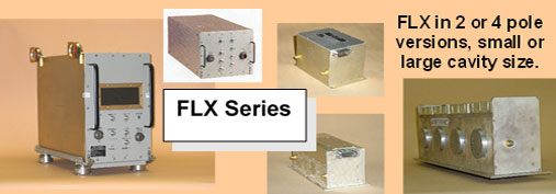
- Filter, Electronic (FLX) for fast tuning.
- A more compact package than VCT or CCT Series.
- Suitable for waveforms that require fast tuning.
- Can be used in frequency hopping or non-hopping modes.
- Compatible with fastest tuning waveforms such as SATURN regardless of dwell time.
- FLX cavities are higher insertion loss than VCT and CCT, but can have built-in HPA’s and LNA’s to compensate
- Available in 30-88 MHz and 225-400 MHz bands.
- Available as single filters through 6-port multicouplers.
- Versions Mil-Qualified for sea, air, and land use.
- For use as a stand-alone product, or as building blocks within our M3B RFD’s.
- We welcome requirements for modification of our existing designs.
CENTER CONDUCTOR TUNED SERIES
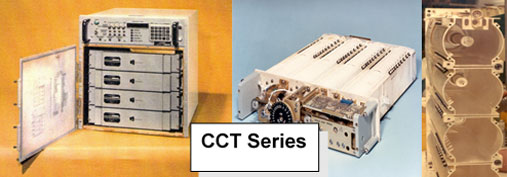
- Center Conductor Tuned filters (CCT).
- Best-of-Breed for naval shipboard UHF multicouplers, providing best transmit power handling, selectivity, and insertion loss for its size and weight. Used on all US Navy ships fleetwide, and many Navies around the world.
- Larger and more rugged (e.g. shipboard shock) than VCT series.
- Typical 5 second tune time. Typical 2 dB insertion loss, depending on selectivity tradeoffs for narrow or wide passbands.
- Various filter cavity sizes available for range of tradeoffs on size/weight versus selectivity, power handling and insertion loss.
- Filter used in transmit and/or receive. Very High transmit power handling (higher than VCT)
- Available in 116-150 MHz and in 225-400 MHz versions.
- Available as single filters through 4-port multicouplers.
- Versions Mil-Qualified for shipboard and land use.
- For use as stand-alone products, or as building blocks within our M3B RFD’s.
- We welcome requirements for modification of our existing designs
All filters are available in various physical cavity sizes suitable for a customer’s specific application. Filters available in multicoupler configurations to combine from 2 to 5 transceiver to a common antenna.
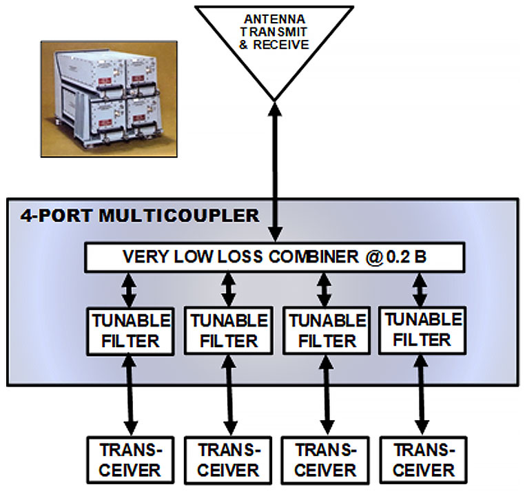
RF Solutions begin with tunable bandpass filters which are utilized in transmit and/or receive modes. VCT and CCT filters can be used individually or assembled as modules that plug into a combiner. The filters and combiner are a multicoupler. Most typical design enables SIMOP of 4 transceivers on 1 antenna.
All combiners (including 4-port) are extremely low loss, typically about 0.2 dB, and add virtually no loss to the tunable bandpass filter loss spec.
FLX filters can be combined, usually including amplifier modules.
SPECIFICATION: NOT SPECI-FICTION!
Leave one letter out of the word “Specification” and you have an entirely different concept which is ripe with risk. RF PRODUCTS leaves nothing out of its commitment to contract performance.
- Proven, existing RF Building Blocks.
- Proven RF Distribution Packaging Approach.
- Very Early, Pre-RFQ support to end-users and platform integrators helps ensure that the overall program is adequately funded and that the solicitation’s platform technical requirements fully define low-risk Comms Capability & SIMOP.
- Detailed Design Support in the Prime Proposal stage ensures maximum risk reduction in our Prime Customers’ Proposals – both technical and price.
- Proven 30+ year track record of delivering on-time and to-spec.
- Not even one contract (none) cancelled due to default. Have never been in litigation, arbitration or court with our customers.
In each Program stage, from earliest pre-RFQ concepts, through requirements statements & proposals, to delivery, fact is never replaced by fiction, and a Program becomes Good Business for everyone.
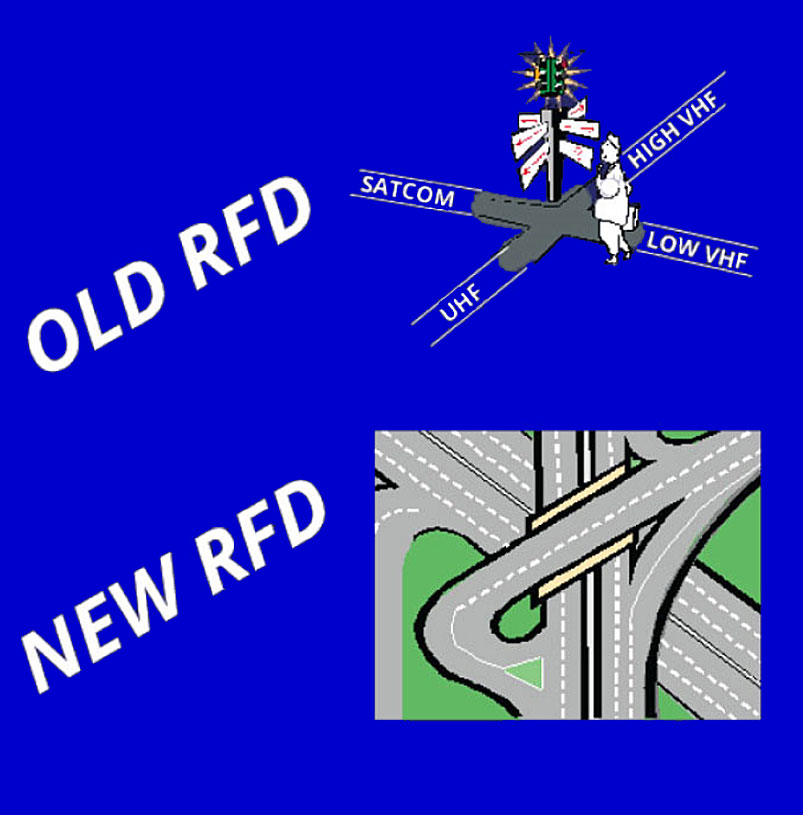
2. MULTI-MODE, MULTI-BAND, RF DISTRIBUTION SYSTEM (M3B RFD), with RCU & R2D2TM
A modern M3B RFD avoids the problems of legacy radio systems:
- Traffic jams
- No alternate routes
- Slow single-lane traffic
- Frequent collisions
Legacy RFD concepts do not provide the RF infrastructure required to handle:
- The voice/data traffic volume of today’s missions, or
- The speed and capabilities of modern M3B transceivers and waveforms.
RF PRODUCTS’ M3B RFD handles the speed and traffic volume of, and provide alternate routes required for, modern "vehicles" (M3B transceivers) which are required for successful military missions. RF PRODUCTS M3B RFD also enables modern and legacy radios and waveforms to share the same platform infrastructure.
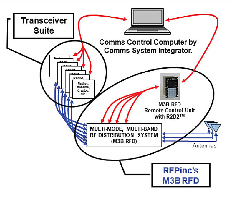
An M3B RFD is non-stovepiped and requires a non-stovepiped seamless remote control system to enable "traffic regulation" in a complex RF infrastructure.
RF Products’ M3B RFD’s are designed for use with RF Products’ Remote Control Unit (RCU) and RF PRODUCTS” RFD RCU Digital Dashboard (R2D2TM).
Just as each scalable M3B RFD design is from common building block boxes, the RCU with R2D2 utilizes common programming that is modified for each M3B RFD/customer specific requirements.
This dramatically reduces cost and risk.
3. COMPLETE RADIO/M3B RFD/ANTENNA SYSTEM DESIGN AND ANALYSIS
Since 1921 RF PRODUCTS has provided the RF building blocks required for communications systems. Today we can:
- Design the complete radio system with you.
- Provide a packaged M3B RFD reducing installation costs while improving RF performance.
- Provide detailed RF performance analyses for the overall radio/M3B RFD/antenna system.
In the proposal stage, we reduce time, technical risk, and writing budgets. In the contract performance stage, we ensure overall radio system performance with minimal risk to your compliance with contract specifications, schedule, and cost budgets.
40+ years of experience in overall radio system specification and RF distribution hardware production, we understand:
- Mission needs, platform integration, and how to define overall requirements.
- Hardware costs versus platform comms goals, and how to help make funding decisions accurate and on target both before and after contract awards.
- System hardware down to the smallest part, and how to eliminate technical risk.
- How to help at any stage of the program: From Government Program Manager’s Pre-RFQ funding requests, to Prime System Integrator’s Post-RFQ proposal preparation.
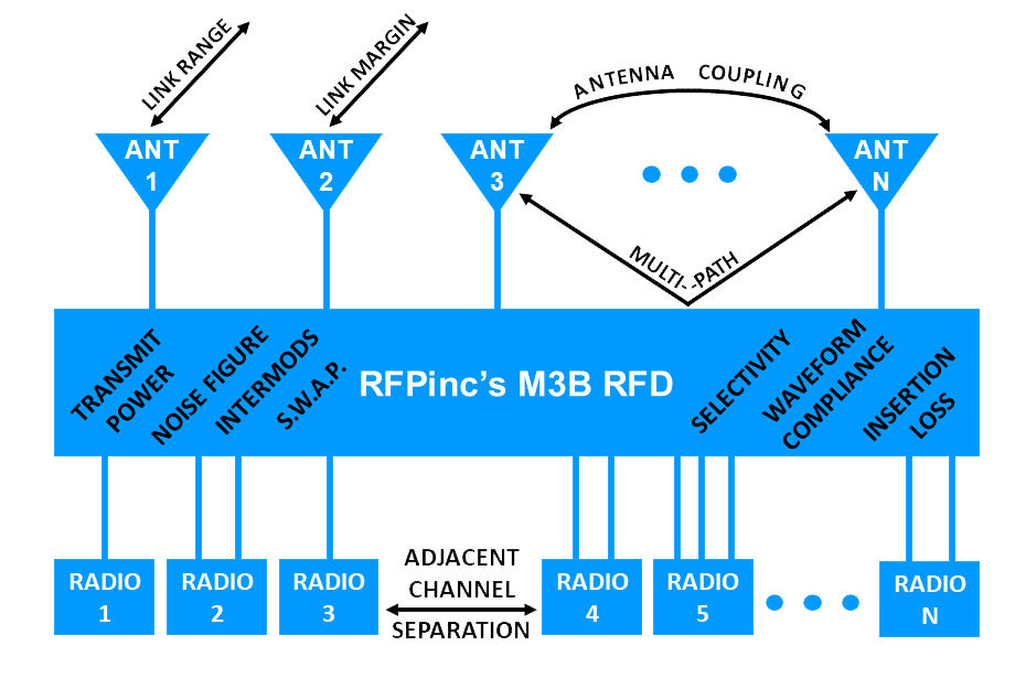
PER PATH ANALYSIS
We calculate the RF performance for each M3B RFD path based on our database of catalog and measured performance of system building blocks and on waveform compliance. Per-Path data is used in the 3 RF analyses shown to the right.
LOS LINK RANGE ANALYSIS
We calculate the LOS link range for each radio and each M3B RFD LOS path. If a link range is insufficient, we quickly and easily determine and make the M3B RFD component value adjustment or change.
SATCOM LINK MARGIN ANALYSIS
For each radio and each SATCOM path through the M3B RFD, we calculate the SATCOM link margin. If a link margin is insufficient, it is fast and easy for us to determine and make the M3B RFD component value adjustment or change.
COSITE INTERFERENCE ANALYSIS
We determine cosite interference for all paths between M3B RFD transmitters and receivers. This information is used to determine minimum frequency Adjacent Channel Separation (ACS) for all combinations of RF paths through the M3B RFD.
I KNOW, THAT’S A LOT OF INFORMATION
Reach out to us with any questions. Our experts are here to help.
Call Us